Thanks
@SyntheticAtmosphere ! Good video to teach someone - although the alternator did fail, it was due to an issue of the communication side of it. The "default strategy" it would otherwise follow is much like the older types, they tracked load by observing the output - to the line going to the battery, and another line came back from the dash (ALT Light) using an Incandescent lamp - When loading was nearly equal (Battery fully charged) the dash ALT lamp hardly had any current thru it so it looked like a nearly zero ohm resistor.
The new dashboards use LED - so they don't go out, but also don't require a lot of current - so the monitor was thru the PCM to check the health of the charging system and keep things running.
The older style works on the older Lamp bulb filament - and how it reacts to power flowing thru it, as power flows thru it, it can change the filaments resistance or appears as a load across that power. IT consumes power to heat and light that filament.
- In the current Fiesta and other Fords' The PCM sends and gets back - data from the Regulator and the PCM tells it to do this or that because of the PCM's own choice of load or not (Think AC or Fan or Cold weather Heating of the seats - any electrical load decision made by the occupants of the vehicle - the PCM would "prepare" a plan to budget load and had to send the Alternator a new update)
So it - Alternators Regulator - ran a "comparator" looking at voltage it generates inside it, to the outside return wire - and developed a difference - which then was amplified and that difference was put into the ROTOR side - the spinning side - of the alternator to make it produce more power at the output Terminal from the STATOR.
From Older days, It is when the Battery was low, the dash return to the Alternator was at that same battery voltage, but the Alternator's own reference from it's power side - this difference then makes that ALT lamp start to light up - heating the filament and making it look more like a resistor and not at zero ohms. The Alternators Regulator power was greater than the Battery - so the power flowed into the bulb trying to get back to the battery.
So the alternator kicked in more power - because of the difference the Alternators comparator sees. The LACK of difference at the alternator means the Regulator sees the battery at a given charge. When the Alternators own reference power was higher than the battery - thru that sense lead the (higher push of current) forced the lamps filament to heat up and show some resistance adding to a voltage drop - then the regulator on the Alternator then senses this and boosts current into the output terminal even more to restore a balance - within the route - Battery thru Ignition wire to Dash to Lamp and back to Alternator provided enough of a voltage drop to make the regulation possible
When the Regulation failed or the output of the Alternator was not enough - the ALT light stayed on, or began to brighten - due to the sheer difference in voltage potential was enough to keep it lit. Then as the battery recharged - that light would go out - if regulation could occur and the battery was in good enough shape to receive and hold a charge - this also was a sign to the mechanic that the battery cables were getting too corroded - or a bad battery looking more like a short - they had a high resistance to current in them making the voltage drop too high or the battery having a bad shorted cell, between the two ranges - the alternator was dumping charge into something that could not hold it - and keeping the ALT light lit.
So when a belt goes off the pulley (snaps off broken belt scenario) the pulley stops turning and the alternator can't keep charging - so it sets the ALT light on the comparator has nothing to compare - along with the dash lights starting to dim.
Since the PCM has taken over the job of the regulation and monitoring - the Dash light is not "involved" as a charge status indicator like older systems - so the LED used is for the PCM to isolate and notify you of an electrical problem that needs service - else the system "appears" as if it was an older system, it doesn't use the bulb method of charge and regulation that provided the user an indication of how healthy the charging system is.
So the PCM talks to the alternator and the Alternator talks back to the PCM and if things are "good" every module shuts up and drives the system. It's when one of the systems modules barks back to the PCM - does something (DTC) get left for the Mechanic to review.
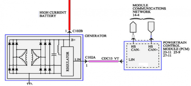
- In the above schematic, the Alternator produces power thru the Regulator that is built into it.
- But...to "boost" power output - the PCM, BCM, ABS and EPAS also have a "Direct line" to the power "company" the Alternator.
- The Violet wire - changes the Regulators workload from "Standard" to higher current - which also is monitored by the PCM, and the on-board Regulator itself at the Alternator - so it does not place wide swings of voltage onto the output terminals that the electrical system could get damaged by - hence the "Monitoring" part.
- The PCM can see the swaying current load and adjust the Regulation by a method of override that lessens or increases the LIN sense output to the regulator and help control load and sense battery condition.
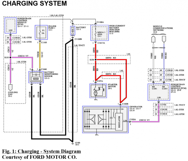
- This system relies on GOOD CONNECTIONS to all systems and points involved to be able to even sense changes and provide performance for the long period of time until the battery or any portion of the electrical system, fails - impacts the entire system if you have any resistive element (Poor contact) in the wire connections - the systems will not work as they once did - if these connection points are neglected.
The Regulators in todays Ford's are a "redundant" system, they will produce power at a given set rate thru the Alternator output post. This works fine for Cars driven a lot of miles or long trips of over 15 minutes at a time, to let the battery retrieve a charge back from the system, but the overall impact is the battery will begin to fail and have less reserve power to start and run the car.
However, The Fiesta uses a replacement Electrical power-assist device that would have run using the output shaft of the engine as a mechanical pump would drive the Power Steering - instead they use the Alternator to provide the electrical needs - for the instantaneous surges thru the system. This is partly the why the PCM is doing the work to develop the budget plan and power needs to keep the system from intermittent or lags in power delivery needed, not to just run the motor and charge the battery - but power the assistive systems on demand without compromising the charging system.
Ok, you may not have needed to know this, but as technology moves ahead - many might need to know this later.